Overview
Document Example of Federating Two Data Sources is base on old version Teiid and JBoss 5, the purpose of this document is use JBoss Data Virtualization 6.x and JBoss Developer Studio 7.x to run this example again.
The document also be keep in teiid-samples/docs/jdv-example-federating-two-data-source.md at master · kylinsoong/teiid-samples · GitHub, it will keep upgrade with the new Product release and upgrade.
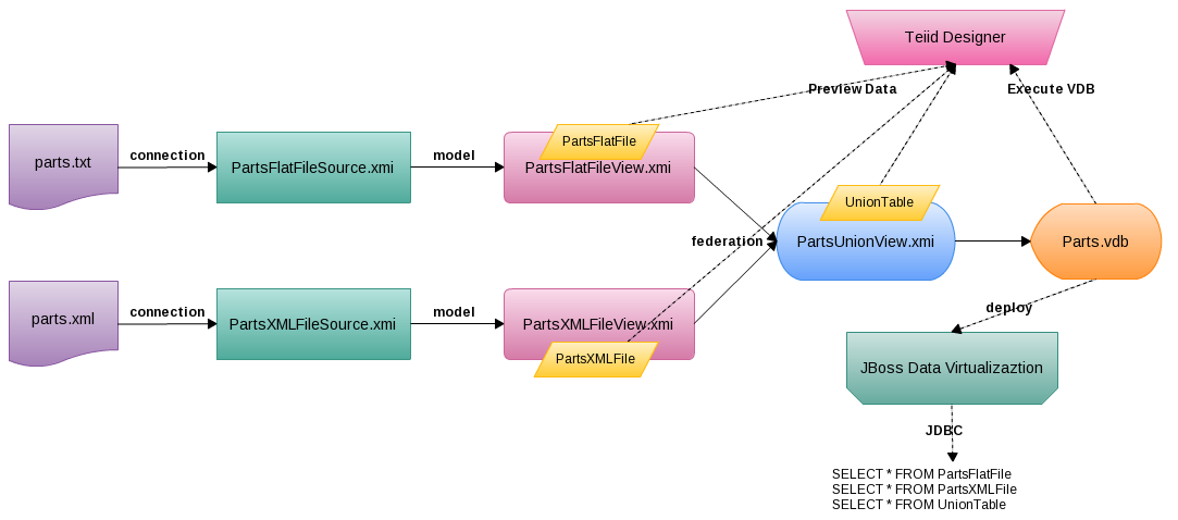
This article presents the ability of Teiid Designer to provide a federated view of two independent data sources. Specifically, it outlines taking an XML file and a text file, creating source models from them and fusing them together in a single union view model.
As below figure
-
parts.txtandparts.xmlcontain different data -
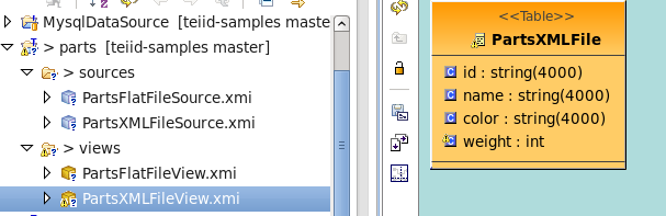
parts.txtbe connected byPartsFlatFileSource.xmiand modeled byPartsFlatFileView.xmi -
parts.xmlbe connected byPartsXMLFileSource.xmiand modeled byPartsXMLFileView.xmi -
PartsUnionView.xmifederating bothPartsFlatFileView.xmiandPartsXMLFileView.xmi -
Parts.vdbcreated base onPartsUnionView.xmi, it can be deploy to JBoss Data Virtualization - Teiid Designer used to Design connection, Design Model, Preview Data, Execute VDB, etc
- JDBC query against JBoss Data Virtualization Server
Requirements
- JBoss Data Virtualization 6.x installed and configured correctly, refer to document for details
- JBoss Developer Studio 7.x with JBoss Data Virtualization Development Tools installed and configured correctly, refer to document for details
Preparing the Data
The data sources to be fused consist of the following:
The files should be copied to a location where both are accessible by the Teiid installation, eg. /usr/share/teiid. Should the teiid installation be located on another host then the files should also be copied to the same location on that host as well since the final deployed VDB does not carry the data with it.
Creating the Project
Open the Teiid Designer perspective in JBoss Developer Studio.
- File -> New -> Other -> Teiid Designer -> Teiid Model Project
- Enter the project name as
partsand choose a location for the project - Click Next> and if the Project References page is displayed, click Next> again (No projects need referencing)
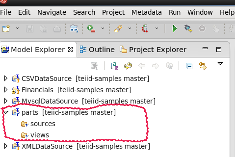
- In the Model Project Options page, only leave selected the
sourceandviewsfolders then click Finish
Import Metadata from a Flat file
-
Import->File Source (Flat) >> Source and View Model, click Next>, enableFlat file on local file systemin Import From Flat File Source wizard, click Next> - In Data File Source Selection page, new Data File Source with name
PartsFlatFileSourceand point to parts.txt - Also in Data File Source Selection page, Source Model Definition section, select Localtion to
sourcesfolder and namePartsFlatFileSource, then click Next> - In Flat File Delimited Columns Parser Setting page, change
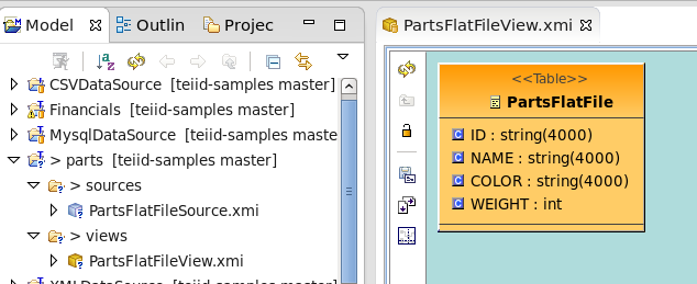
WEIGHTcolumn to interger, then click Next> - In View Model Definition page, select Location
parts/views, NamePartsFlatFileView.xmi, New view table namePartsFlatFile, and click Finish
Import Metadata from a XML file
- In XML Data File Source Selection page, new Data File Source with name
PartsXMLFileSourceand point to parts.xml - Also in XML Data File Source Selection page, Source Model Definition section, select Localtion to
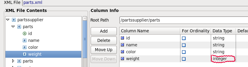
sourcesfolder and namePartsXMLFileSource, then click Next> - In XML Data File Import Options page, select Root Path
/partssupplier/parts, and add column, change theWEIGHTcolumn to interger
- Click Next>, in View Model Definition page, select Location
parts/views, NamePartsXMLFileView.xmi, New view table namePartsXMLFile, and click Finish
Create a Union View Model
Create Relational View Model
- Right-click on the views folder, select New > Teiid Metadata Model to open the New Model Wizard
- In the New Model Wizard, enter the following and click Finish
- Location: parts/views
- Model Name: PartsUnionView
- Model Class: Relational
- Model Type: View Model
This should create a blank PartsUnionView Model Editor.
Create View Table
- In the blank PartsUnionView Model Editor, right-click and select New Child > Table
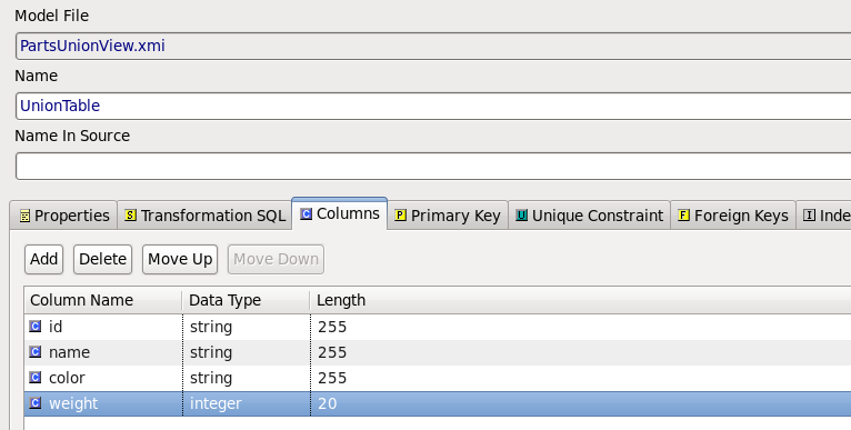
- In prompted Create Relational View Table wizard enter the name UnionTable, Define Columns as below figure then click OK.
Add Source Tables to View Transformation
The view is now ready to be linked to the text and xml source models. This is achieved by opening the Transformation Diagram for the PartUnionView model.
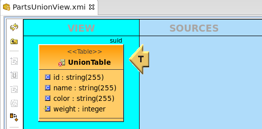
- In the Model Explorer View, expand the PartUnionView node and double-click the UnionTable. The transformation diagram editor should be opened:
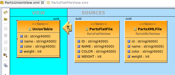
- In the Model Explorer, selecting the PartsFlatFile and PartsXMLFile enables the Add Union Transformation Source(s) button on the diagram toolbar. Click this button to add the two views as sources for the UnionTable as below:
Test the New Model
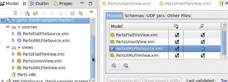
- Create VDB, Select Model PartsUnionView, the source and other views models will be added automatically as dependency models, as below:
- Deploy
Parts.vdb, Run PartsClient as java Application, this will have the following output:
Query SQL: SELECT * FROM PartsFlatFile
1: P300, Nut, Red, 12
2: P301, Bolt, Blue, 12
3: P302, Screw, Blue, 13
4: P303, Bolt, Green, 17
5: P304, Cam, Green, 18
6: P305, Cog, Red, 20
7: P306, Screw, Blue, 16
8: P307, Washer, Green, 19
9: P308, Cam, Yellow, 15
10: P309, Rod, Yellow, 14
11: P310, Cap, Red, 13
12: P311, Wheel, Green, 18
13: P312, Bolt, Blue, 21
14: P313, Nut, Blue, 11
15: P314, Screw, Yellow, 15
16: P315, Fastener, Blue, 14

Query SQL: SELECT * FROM PartsXMLFile
1: P400, Rod, Red, 12
2: P401, Bolt, Orange, 12
3: P402, Nail, Orange, 13
4: P403, Bolt, Green, 17
5: P404, Cam, Green, 18
6: P405, Cog, Red, 20
7: P406, Nail, Orange, 16
8: P407, Washer, Green, 19
9: P408, Cam, Black, 15
10: P409, Rod, Black, 14
11: P410, Cap, Red, 13
12: P411, Wheel, Green, 18
13: P412, Bolt, Orange, 21
14: P413, Rod, Orange, 11
15: P414, Nail, Black, 15
16: P415, Fastener, Orange, 14

Query SQL: SELECT * FROM UnionTable
1: P300, Nut, Red, 12
2: P301, Bolt, Blue, 12
3: P302, Screw, Blue, 13
4: P303, Bolt, Green, 17
5: P304, Cam, Green, 18
6: P305, Cog, Red, 20
7: P306, Screw, Blue, 16
8: P307, Washer, Green, 19
9: P308, Cam, Yellow, 15
10: P309, Rod, Yellow, 14
11: P310, Cap, Red, 13
12: P311, Wheel, Green, 18
13: P312, Bolt, Blue, 21
14: P313, Nut, Blue, 11
15: P314, Screw, Yellow, 15
16: P315, Fastener, Blue, 14
17: P400, Rod, Red, 12
18: P401, Bolt, Orange, 12
19: P402, Nail, Orange, 13
20: P403, Bolt, Green, 17
21: P404, Cam, Green, 18
22: P405, Cog, Red, 20
23: P406, Nail, Orange, 16
24: P407, Washer, Green, 19
25: P408, Cam, Black, 15
26: P409, Rod, Black, 14
27: P410, Cap, Red, 13
28: P411, Wheel, Green, 18
29: P412, Bolt, Orange, 21
30: P413, Rod, Orange, 11
31: P414, Nail, Black, 15
32: P415, Fastener, Orange, 14
Note, from above output, the union view returns the data from two independent data sources. The reference project as workspace/parts.
Comments